I have been growing interest in printing processes and their relation to social movements and civic engagement.
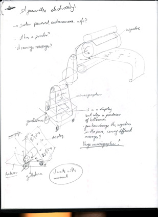
I am building a movable printing cart as part of one of the pieces envolving my research at ACT, the model I am working on is based on lino cut, printing press, offset printing and dampening systems.
I am really interested in the idea of replicability and repetition through time, the fading of the ink and the mistakes this type of machines have.
Automating this machine will bring extra layers of complexity to the work. Repetition, error, movement and the possibility of failure are the main focuses behind this machine.
After doing some research on lyno cut, printing presses and offset printing I got really interested in gear mechanisms as a way of representing multiplicity and joint efforts, I am really appealed on how movement and shape can cause opossing forces to work together and trabslate it to displacement.
History of printing is fascinating and I want to use this opportunity to explore it.
Movement
Movement plays an important part of my recent work as an artist as it is related to bodies and space, being an architect you are trained to contain movement, to control it, but cities are all movement. We are in constant change, an organic mass of bodies moving around changing everything around, leaving trace.
Traces come from movement.
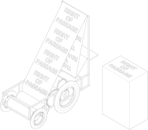
I want a vehicle, a small portable vehicle that moves while leaving trace, a small machine that prints, copies and repeats until it is exhausted.
The mechanism:
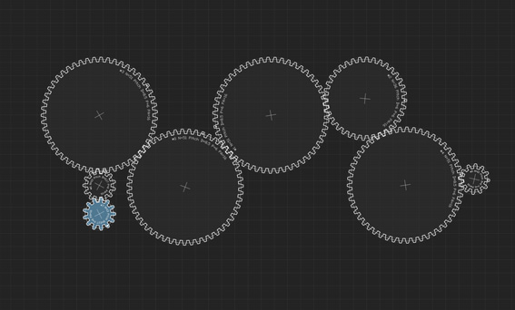
I will be using a gear mechanism with rollers that will act as paper source, roll push, dampeners, and lino cut roll for printing. Iam thinking on ataching a motor to one of the gears in order to power the entire system, this gears will be attached to axels wich will also give structure to the whole system.
After several discussions with TA's, I am thinking on using a stepper motor to power the mechanism, as dc motors are not that string and not so easy to control ans stepper motors cover other functions. One of the challenges with the motor will be hou to attach it and how to design a part that is cimpatible with the gears I have already designed.
Prototyping
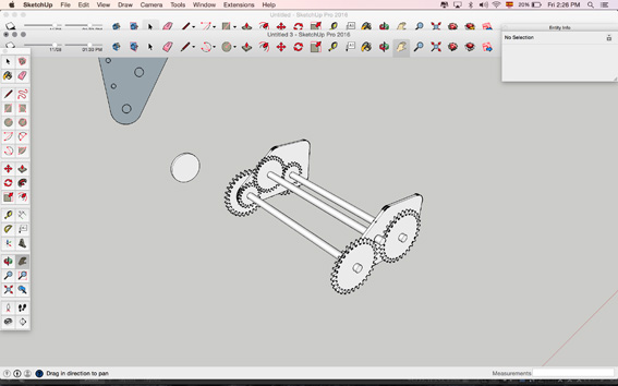
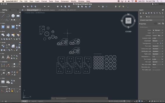
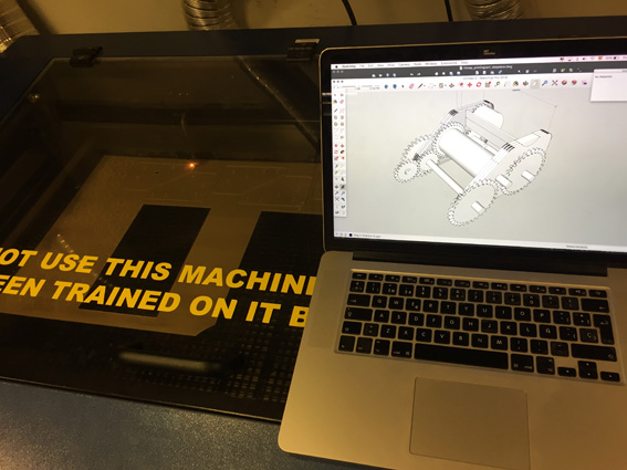
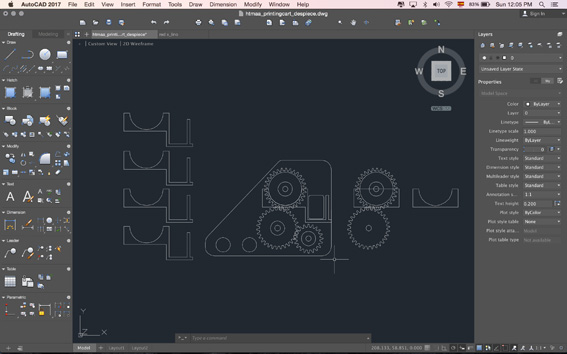
After several attempts on calculating gears, radiuses and pitch diameters I found an online open source gear generator which was very helpfull. I also found some prototypes online of small printers and gears for other types of projects that were also open source. I took this information and redesigned it in order to fit what I am trying to achieve.
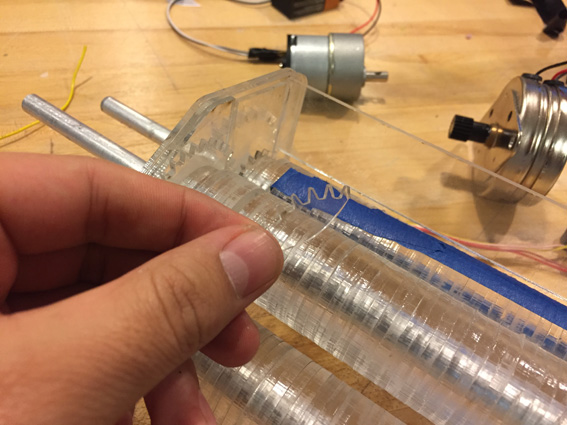
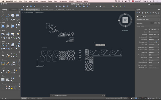
I decided to work with acrylic because I like the mechanism to be as exposed as possible, transparency gives it a very special, clean look. I started making some drawings on AutoCAD as it is easier for this purposes for me and then exported it to Sketchup, I know other programs could have helped but for practical purposes I decided to do it this way. Parametrizing the holes for the axels is a very good idea as well as the junctions for the assemplage of the pieces.
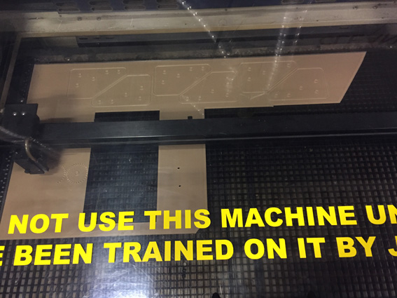
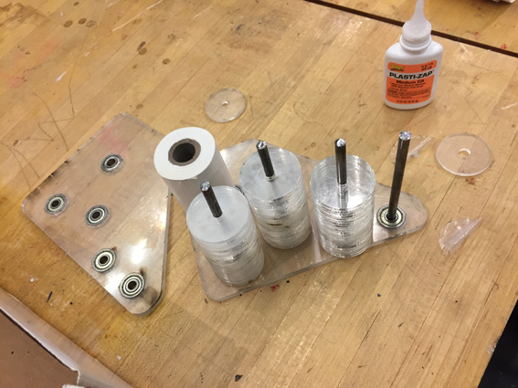
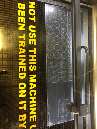
I used a 3mm thick acrylic to laser cut the file I just designed, everything was designed to fit this 3mm thickness; I gave a margin of .5mm to the pieces tat had to fit tight and they worked really well.
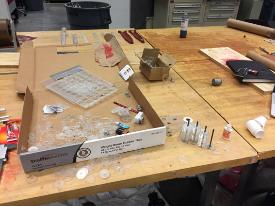
I used stacked circular pieces of acrylic to make the rollers also thinking on repeating the transparency idea and they came out quite well, the laser cutter had some issues cutting through the entire thickness of the acrylic but it was a matter of just repeating the same file and cutting everything again.
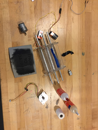
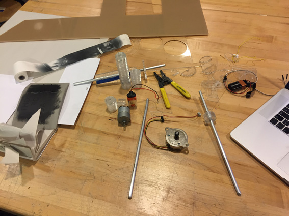
I cut the 8mm diameter axels rods in the metal workshop and came out really clean. I oversized them in order to handle the mechanism. I encountered several issues while doing this first prototype:
Rotation of the rolls joined to the axel was hard and I have to find a way to attach them but not permanently as the rolls will have to be changed eventually.
As the mechanism begins to be enclosed with the walls I start getting a lot of torsion and deformation in the whole machine, different forces start pushing and pulling towards different directons as the machine is not well balanced.
Lyno cut thicknes is going to be a big issue as it has to touch and pressure the paper but not pressure so much so that the mechanism is as smooth as possible.
Ink is also a big issue as the rollers are dependent on constant flow of ink, I realised the dampening system has to be on the bottom of the lyno cut roll so that gravity doesn’t make a mess with the ink dripping out of the case.
Wheels will have to be attached to the axels but one side of them has to be detachable so that rollers can be changed over time.
Width of the rollers have to responf to the width of comercial paper rolls, the prototype has to be smaller in width.
Two more rollers have to be incorporated for the motor and the paper causing a change in the design of the walls of the machine.
I have to come up with a detachable mechanism in order to assemble as many pieces as possible, avoiding glue.
Lyno can be rastered in the laser cutter pretty easily, I will try to find a way to roll it so that it doesnt break as it has happened 2 or 3 times before, if not I will be considering different materials like rubber or other more flexible workable surfaces.
Second prototype
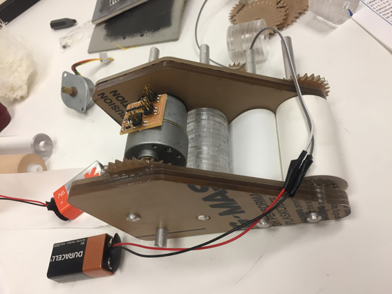
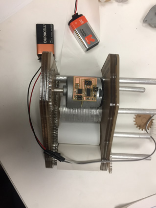
The second prototype considered all of the points mentioned avobe and the change of design came out quite well.
A lighter smaller version that has two more rolls and has upper space for the motor, the battery and the board. Assemblage was quite easy. Scale is really nice.
After doing some research on comercial small scale rolls of paper I found thermal paper rolls to be the best option for the project, 2 1/4" width x 127" rollers, They are small enough in width and very large in lenght. (A further note on this paper is its thermal qualities that could potentially be an iteration for the project).
Further challenges:
Least amount of glue in assemblages.
A 3d printed 10mm to 8mm adaptor for the thermal rolls, in this way they can be detachable also. Doing some observation on plotter roll mechanisms.
More space for the thermal paper roll, this implies a third iteration on the design of the walls.
Motor, battery and board storage in the machine, this has to be well thought as it has to garantee the conection and torque for the motor and the rest of the machine, everything has to be held really tight. Still making some changes in the type of motor I will be using so this part of the design will have to wait until I have defined the motor. There is also a great chance for moulding and casting in this area.
Electronics
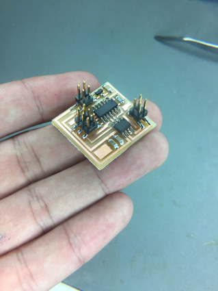
As I dont know wich motor will be best for my machine I decided to try all of them. I started milling a board for a Servo motor, it kept on burning but I later realized I had only a 10uF capacitor while the circuit needed 22uF, after navigating much of prior year webpages I realized you can stack them and create a 20 or 22uF capacitor, I did and then tried to program without any luck. My guess is that the chip fried.
Moving on...
After a TA session with Teja, he mentioned DC motors and the possibility to attach it to gears or other mechanism, Teja was really helpfull as he told me about lots of ways I could get this mechanism working. He also mentioned the possibility of incirporating a button or switch in the board so I can get the input-output interaction that I want to accomplish.
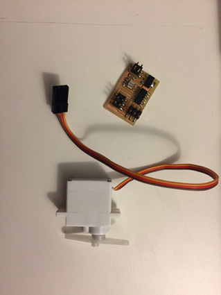
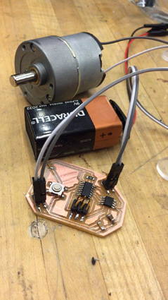
After this session I decided to try out the DC motor, I succesfully milled and solder the board and with the help of Po Hao I was able to program it with the C code available in the webpage. I proceeded to connect the DC motor to the chip, wich was also connected to a 9v battery but the motor never responded.
I plan to make another Ta meeting in order to see what I am doing wrong and get my motor runnig so that I can play with the C code.
Later on the week, talking to Alfonso from CBA about my project he mentioned stepper motors so I decided to try to mill and solder that board also. I did some research on stepper motors and decided to use de unipolar one as I dont need so many functions in the motor.
Getting a motor working, doing more research on the ideal one and playing with the C file is one of the main tasks I have for these next weeks.
I had a very productive TA session with Diego who told me more stuff about motors and the type of motor I should be using for my project, we tried some stuff with my DC motor board which was already programmed and it didnt move at all, at least it didint seem to move.
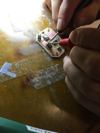
After checking the soldering we checked the connections with the multimeter, this process was very helpfull as you can really see what is wrong with your connectiones and it is very easy.
Everything seemed fine with the multimeter and the soldering so we proceded to check the direction of the components, to do this we went through several datasheets available online and everything seemed fine.
Next step was the coding.
I was using Neil's code for the DC motor and everything seemed fine, we decided to supress the whole code and just get the motor running with the simplest code. I saved the file and programmed the board and the motor worked!
I was very excited but this didn't meant total success.
After several attempts the motor kept on failing so we decided to dig deeper on the code. Everything seemed correct.
After playing for a while with the parameters, I changed the delay on one of the commands and tried again, this got the motor running and doing what it was supposed to do in the first place. Apparently, the delay depends on the motor you choose, this timer can be different depending on what you want to do with the motor, every one of them has different characteristics and works with different delays.
My task now is to figure out the delays necessary for the motor I will choose in order for the whole piece to operate, this is critical because I need to house the motor into my main structure so I need my final motor in order to have the exact shape of it considered in my printing cart.
I am planning on seeing more TA's in order to understand what type of motor is better for me.
good news is that my motor actually works and I just have to play a bit with the code.
Next I will try to have the code and attach a button so that the whole system works with just one click of a button.
Incorporating a button on the dc motor board was tricky, I went through a lot of past years projects and finally could understang how to make the schematics to incorporate the button. As I want the printing press cart to move while printing and kind of go away I just need the button to act as a switch.
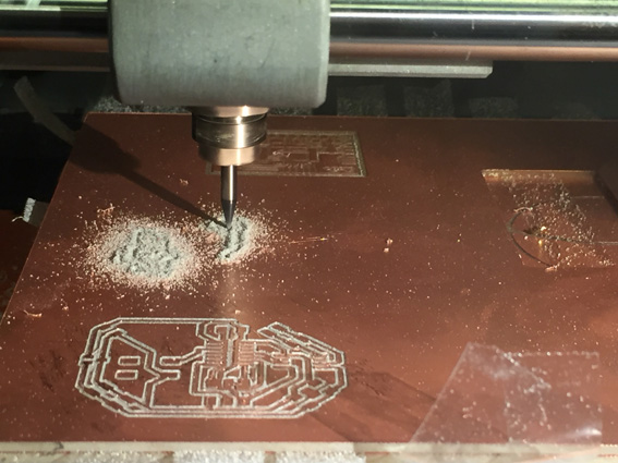
Getting all the components from the library and making the board design was tricky as always, Eagle is a great tool but also quite messy if you don't know how to manage it. After spending some time getting the board right and seeing other examples from other years I finnally got it right, choosing the components was quite complicated as I have to spend a lot of time looking for them while milling the board. I had some trouble also with the size of the board as Macs work in different resolution as other computers, I tried milling the first board and it came out double the size, after that I did the calculations and changed the DPIs directly in Mods in order to have the exact size I wanted, in this case it meant changing from 500dpis to 999.9 dpis.
The milling was quite messsy and it did a very bad job as the endmill was old, also I relized that the resolution of the png had eaten a lot of lines that the Roland was not respecting, it kept on doing double lines and joining them together which is very bad for the circuit.
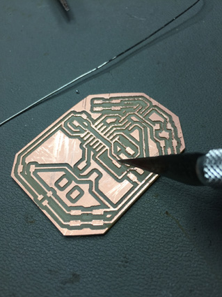
After observing the calculations from mods I realised the conections from my design were too close from one another and I had to go back to Eagle and change the parameters, turns out I forgot to download the design rules from the library, also I changed the grid and moved the traces further apart so that they didnt tpuch while milling.
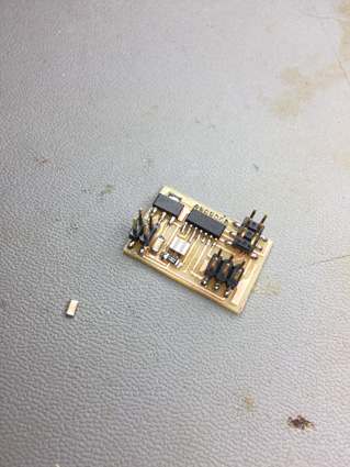
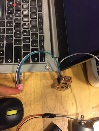
I saved the png and milled the board for the third time, this time everything seemed correct, I took the components and proceded to the soldering.
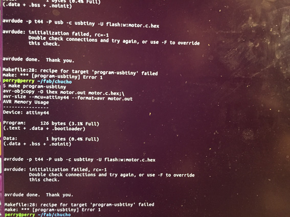
soldering was very therapeutical as usual and I got it done very quickly, I tried to program the board but it keot on giving me error -1, fortunately Eyal was around and was willing to helo me, we checked the board with the multimeter and it seemed like some of the pins from the attyny 44 where connected amongst themselves, I had to go back and effectively I hadn't realised the traces were joined together as they where still very close to each other.
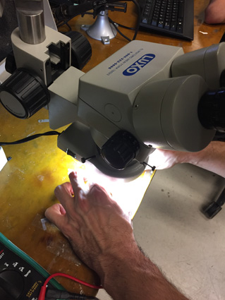
I looked at it with the microscope and effectively it had all of the pins from the microcontroler joined in one trace, I proceded to desolder the piece with the heat gun and the desoldering piece which was very useful, I cut the traces that were joined and took a lot of debris from the milling. I resoldered the Attiny 44 again and proceded to program it again.
No luck again, error -1 again. I started getting desperate but Eyal was around again to help, we checked again with the multimeter and finally got that one of the 2x2 headers wasnt giving any current, I looked in the microscope and effectively the machine had eaten part of the trace and it was very very thing, I had to desolder again with the heatgun and the desoldering tool, make a soldering bridge in the trace and reconect the piece again.
SUCCESS!!
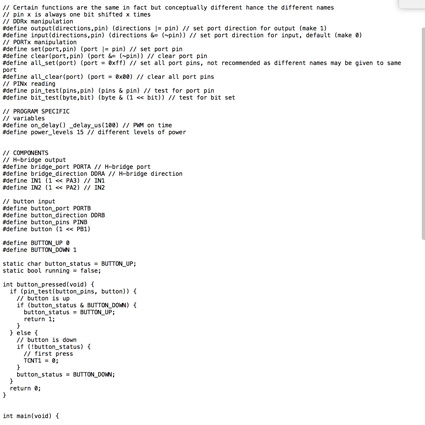
It felt amazing, I programmed it with pieces of neils code and other classmate's code in order to make the button to work.
pressing the button and looking at it move was amazing, I felt so good. I would say its close to magic.
After that I was looking for the cart to advance whenever you pushed the button so I played with the delays with the help of eyal, I gave the motor a time window of 10 seconds everytime the button was pressed, this was kind of tricky because of the timer on the Attiny, forst time it came out very slow, then it was too fast and then we could hit it by joining some more code from Eyals work with other previous motors. It was really amazing to learn how you can take pieces of different codes and it would still work, also the datasheet was quite usefull as it has the commands to tell the clock what you want it to
do.
The code came out a little bit messy but it was totally worth it. I succesfully made it work so that it moved for 10 seconds with the speed I wanted and it worked everytime.
This felt amazing!
Going back to the prototype:
After talking to Alfonso about my project he sugested to incorporate bearings, he was kind enough to give me some bearings he had in his lab to incorporate them to the design, this meant I had to change and draw the whole prototype again. As I was drawing it I made some more changes in order to incorporate the battery, the cables and the chip in the upper part of the little cart. I changed the diameter of the holes in the walls of the cart and also the diameter of the holes for the axels. Bearing are so incredible and easy to use, and they really improved the feeling of the little cart. They fit perfectly to the prototype and I only had to put some glue on the in order for them to stay fixed.
I discovered the bearings Alfonso gave me had same outer diameter but different inside diamet amongst themselves, this was quite tricky because I was calculating everything to fit for one type of diameter, this meant I had to cut almost all the pieces again.
The decission to use acrylic and laminated was really nice as it gives a really clean and nice look to the cart, also I was looking for the mechanism to show and it did it in a really nice way. If I could change something in the assemblage process I would change the type of glue, it was really smelly and stained the acrilyc in a very bad way. The prototype ended looking a little bit messy but still beautyfull.
Linocut roll:
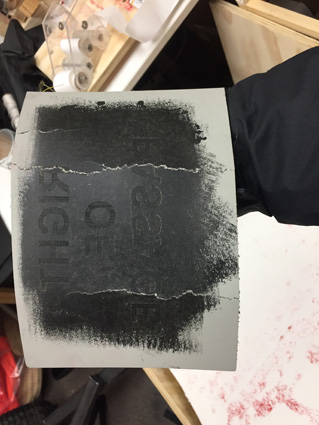
I did some tests with the linoleum I bought for the project with the different traditional tools, after thinking a bit about it I decided to try to use the laser cutter to raster the lino and maybe get a very sharp result. I asked Tom if it was a good idea as I saw some tutorials on youtube that did it with very good results.
Words came out pretty well and the process was really fast. This was an amazing discovery as you can have very complex images in a very short time and a very faithfull transfer. Obviously the linocut traditional techniques have a very interesting feel to it but this seems like a different way of making prints.
The linoleum proved to be a great material until I got to roll it out, as lino is a semiflexible component it doesnt resist a lot of flexing, after several attempts the lino broke and the roll was unable to print. This was a very bad news as I was already out of time to try a new material for the roll, I even tried with rubber but when etching it in the laser cutter it was very smoky and didn't seem like a good option.
One possibility would be to 3d print the roll with the image or the relief already in the roll, other would be to try it out with a different more flexible material so that it can roll in the diameter I want, and other really interesting also would be to make a mould with oomoo and then cast it and make it with rubber, this would be tricky as I need to have an axel right in the middle of the roll and also a gear at the very end of the roller. I will try to fix this breaking problem for the future as I think it is a very important part of the process.
Ataching the motor to the gear system:
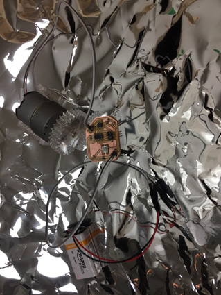
Everything is very easy when you model it in a 3d environment but when it comes to reality a lot of factors play and end up messing a lot of things you havent expected. While attaching the motor I had to fix it to a base I had designed that contemplated the diameter of the DC motor, I glued everything together and atached the last gear of the system to the motor expecting that when everything was connected and in place, I could press the button and the system would start moving while also printing.
Turns out I pressed the button and as it was forcing the gear system it detached the entire prototype, messing around with the wheels, the axels and the rollers, this was bad and good news, bad because I ran out of time in order to fix the entire system but good because the motor was powerful enough to move the entire system, I just have to adjust it in a better way.
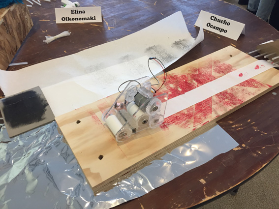
At the end I ended uo with a functioning prototype that oncorporated a gear mechanism that moved the entire system in order to take paper, roll it and print it. A functional board programmed succesfully to operate the motor at the speed and time necesary and a broken laser cutted lino cut that makes very interesting and faithfull prints.
I learned a lot and I felt great when I got all of the pieces working, even if they worked independently and didnt like to work together I would say it was a succesfull project.
What does it do?
The aim was to make a movable linocut replicator that is operated by a dc motor controlled by a board activated by a button.
Who's done what beforehand?
Linocut replicators have been around for a long time, Linoleum was originally invented to replace industrial floors and hospital floors, it was a durable composite that was water repellent and also very cheap to manufacture. It started being used by printmakers and engravers as an alternative to Xilography or woodcut. Linocut rolls are not so popular due to the time it is required to do them and also the properties of the materials, by changing and using the laser cutter I am proposing a new way of making linocut prints. this will never compare to the manual procesess and craft the original linocut engravers use but it can be a really interesting alternative to linography and replicators.
What did you design?
I designed the gear mechanism and the whole prototype of the printing movable cart. I managed to create 4 iterations of the same prototype learning from everyone of them, and always changing and adjusting little things in them. The desigh process was quite nice and I really enjoyed assembling and getting everything to work. I also had to do some research on gears and had to understand how different diameters of gears work, pitch diameter, calculations of force between evey shae and also the forces that are applied in the whole system.
What materials and components were used?
I mainly used acrylic as I wanted to show the entire gear mechanism, acrylic was obtained from scraps from the shop and I didnt had to buy anything except the linoleum. The bearings were generously provided by Alfonso from CBA, and the axels were available in the mars lab. The motor also came from the CBA and the battery that was used was also part of the inventory of the shop.
How much did they cost?
All of the materials used for the project were already in the shop, scraps pf acrylic from other projects, and motors were already available in the shop. Everything was collected at MIT except the linoleum and some tools wich were bought in Blick.
What parts and systems were made?
All of the parts of the printing cart were made in the shop using acrylic and the laser cutter, axels where cut down and sanded in the welding shop and linocut roll was rastered and folded in the shop also. The only ready made components from the project were the bearings, the roll of paper and the motor.
What processes were used?
3D and 2D modelling in Sketchup, Autocad, Fusion, Illustrator and Corelx.
Electronics design in Eagle, Milling boards with the Roland machine, soldering and programming.
What questions were answered?
Maching an automated mechanism is really hard, even if it is small, one has to take into consideration every small detail as it is going to be crucial when the work is almost done. Work in cycles trying to complete symple tasks and the adding more complex layers to the project.
How was it evaluated?
I believe that with the very short experience I have I managed to do a lot of breakthrous through this project, programming and electronics were very hard for me during the semester so being able to make this work at least in parts is a very succesfull stage for me, I am really happy with the result and I am proud of the work I have done in the class, it will continue to help me in my practice and for sure will make me think of projects in a very different way.
What are the implications?
One has to suffer a great deal in order to make something really work, the implications for something to be succesfull are incredible and being able to align all of them is a very difficult task but also extremely rewarding. I learned a lot about how things work and how I can make things work in different ways in this class. Getting a little bit closer to have something that actually converts information and code into movement and a machine feels very empowering.


 I looked at it with the microscope and effectively it had all of the pins from the microcontroler joined in one trace, I proceded to desolder the piece with the heat gun and the desoldering piece which was very useful, I cut the traces that were joined and took a lot of debris from the milling. I resoldered the Attiny 44 again and proceded to program it again.
 No luck again, error -1 again. I started getting desperate but Eyal was around again to help, we checked again with the multimeter and finally got that one of the 2x2 headers wasnt giving any current, I looked in the microscope and effectively the machine had eaten part of the trace and it was very very thing, I had to desolder again with the heatgun and the desoldering tool, make a soldering bridge in the trace and reconect the piece again.
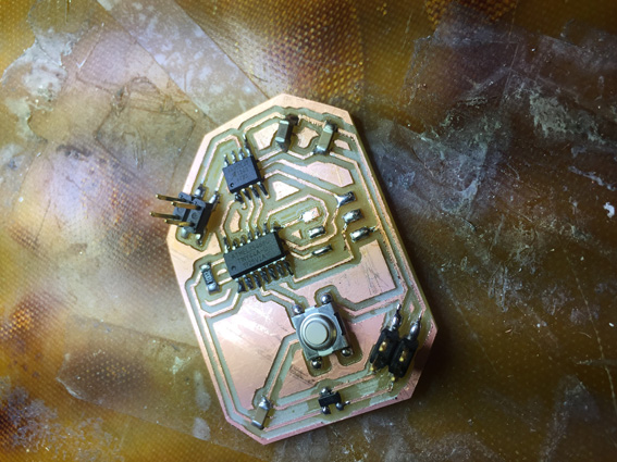


 This felt amazing!
 Linocut roll:
 Ataching the motor to the gear system:
 Everything is very easy when you model it in a 3d environment but when it comes to reality a lot of factors play and end up messing a lot of things you havent expected. While attaching the motor I had to fix it to a base I had designed that contemplated the diameter of the DC motor, I glued everything together and atached the last gear of the system to the motor expecting that when everything was connected and in place, I could press the button and the system would start moving while also printing.